
The Amplfier Design Wizard is a powerful design tool that assists the design engineer with modelling transistors, pads and parasitcs and guides the engineer though systematic topology searches to get optimal results in amplifier design and impedance matching.

The Ampsa Amplifier Design Wizard (ADW) takes a new approach towards amplifier design.
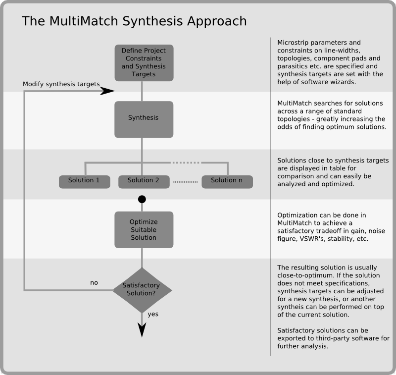
The prevalent approach to the design of RF and microwave circuits today is still the optimization approach. An initial solution is obtained by some means or other, and this solution is optimized (improved by using optimization techniques) with a general-purpose RF and microwave circuit simulator. While this approach is certainly workable, it is slow, depends heavily on the experience of the designer (or some other source) and often yields inferior results. The requirement of initial solutions is also a major drawback.
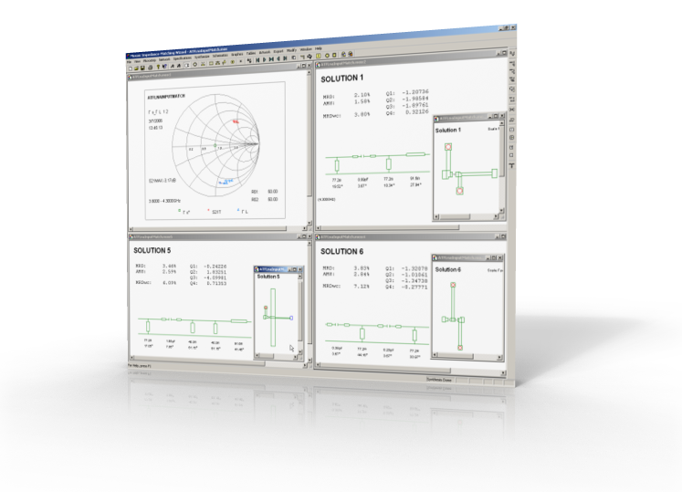
(hide)In the Amplifier Design Wizard, the basic point of departure is that one cannot rely only on optimization techniques to find close-to-optimum solutions. A solution to this problem is to find solutions by doing systematic searches. A simple grid search is, however, not the answer. In order to do the required search efficiently, the search must, in the first place, be done on the correct parameters and, secondly, it should be synthesis based. A number of the best solutions found in the systematic search are then optimized, after which the user can choose the best solution from the potential solutions presented.
The systematic searches also eliminate the initialization problem.

The ADW is comprised of various modules.
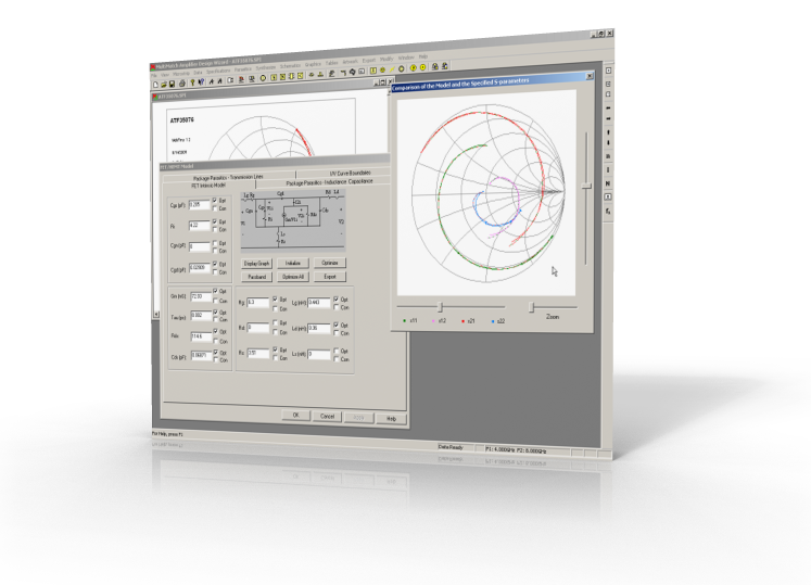
The capabilities provided in the Modeling Section include:
Modification sections can be synthesized or added manually to the transistor in the Modeling and Modification Module. A modification network consist of frequency selective resistive feedback and/or resistive loading sections. These sections are used to pre-condition the transistor for improved stability, flat gain response, lower VSWRs (before synthesizing the matching networks required), as well as to have low VSWRs at the same time as a low noise figure and/or high output power. Sophisticated modification network synthesis techniques are implemented in the Amplifier Design Wizard.
read more...
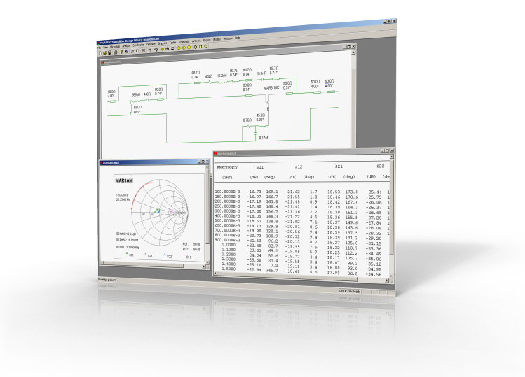
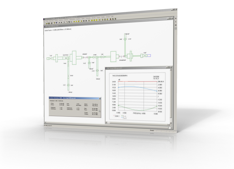
The S-parameters and noise parameters of any Amplifier Design Wizard (ADW) circuit can be calculated in the Analysis Module (Extended cascade analysis, as well as nodal analysis are allowed). The stability of the circuit can also be evaluated. Stability analysis includes calculation of various stability factors, as well as loop gain and reflection analysis. While only linear circuits are analyzed, the 1-dB compression point of amplifiers can be estimated too. The performance of the drivers in an amplifier chain is also calculated. Tuning and optimization capabilities are also provided in the Analysis Module. The optimization capabilities include optimization of the performance of a linear amplifier, as well as optimization of a model to fit a set of two-port parameters. Instead of optimizing a circuit, the harmonic content assumed for a transistor can also be optimized to fit the measured performance of the circuit or the performance obtained in a harmonic-balance simulator.
Various wizards are incorporated into the Analysis Module. These wizards set up transistor modification problems, as well as a variety of impedance-matching problems. The problem defined by a wizard is then solved by using the relevant Synthesis Module.
Note that load-pull contours can be generated by the CIL Wizard to find the 1dB-compression points of a transistor. The contours can be generated even when feedback or loading is applied to a transistor. (The transistor configuration may be changed too.) The default selection of the best point on each contour can be modified by the user. This allows greater control over the performance of the amplifier.
read more...
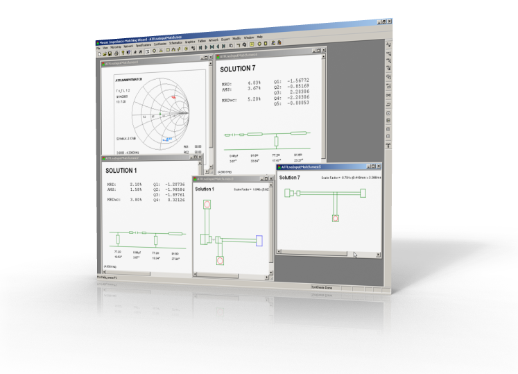
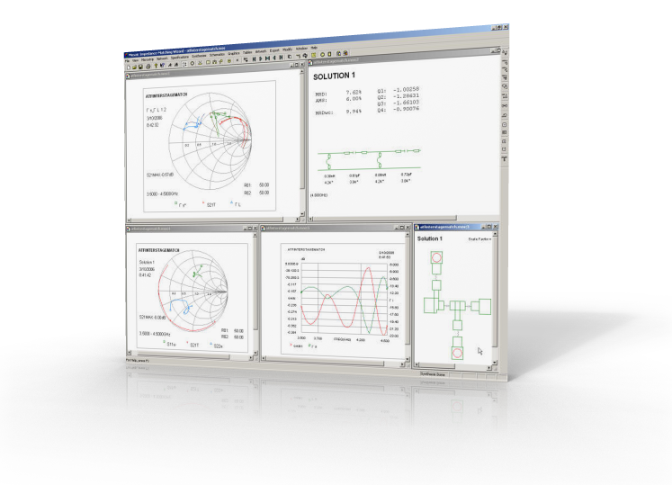
The Impedance-Matching Module is used to synthesize lumped-element, distributed or mixed lumped/distributed matching networks. Wizards are provided to synthesize commensurate (equal line lengths) and non-commensurate networks.
When commensurate networks are synthesized, the lengths of any main line sections, open-ended stubs or short-circuited stubs are specified by the user and the widths are used as variables. Different lengths may be used for the main line sections, open-ended stubs or short-circuited stubs. If the stub lengths are kept short, the stubs can be replaced with lumped components in the Analysis Module. The line widths or characteristic impedances can be constrained. It is a good idea to initially leave these unconstrained and to observe the impedance values required, as well as the performance that can be obtained when this is done.
When non-commensurate networks are synthesized, the widths of any main line sections, open-ended stubs or short-circuited stubs are specified by the user and the line lengths are used as variables. Different widths may be used for the main line sections, open-ended stubs or short-circuited stubs. The minimum and maximum lengths of the main-line sections can be constrained. The minimum length constraint is often essential to ensure that the any stubs used are separated sufficiently. When mixed lumped/distributed networks are synthesized, pads can be specified for the lumped components too. The lumped components in these solutions are used to reduce the size of the network.
read more...

Ultimate Performance. The ADW has a reputation for delivering first-time-right designs with performance superior to that attainable by other design techniques.
Much shorter design cycles. The synthesis techniques implemented lead to more robust designs that require less tuning and trial and error efforts to achieve the most challenging specifications. This translates into faster and fewer design cycles and hence increased productivity.
Comprehensive export capabilities. If required, the microstrip | stripline circuit designed can be processed further with a general-purpose microwave simulator. To ease the transition, the following export capabilities are provided:
The Amplifier Design Wizard is a Visual C++ 2022 Unicode MFC (Microsoft Foundation Class) WindowsTM application. Several design wizards have been implemented in the Amplifier Design Wizard in order to simplify complex tasks.
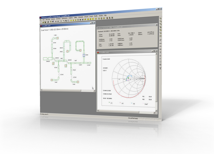
The Amplifier Design Wizard can automatically transform the electrical description of a designed circuit into microstrip or stripline form, with automatic compensation for discontinuity effects. The artwork can be displayed and modified graphically in the Analysis Module, and can be exported in various formats.
To find out more about the Amplifier Design Wizard's features and capabilities, be sure to view some of the screencasts provided and refer to the following articles, documents and book.

Windows 7TM, Windows 10TM or Windows 11TM is required to run the Amplifier Design Wizard. Windows 11 is recommended for the ADW.
The minimum recommended hardware requirements are shown in the table below.
| Processor: | 1.5 GHZ |
| RAM: | 4 GB |
| Graphics Resolution: | 1680x1050 px |
| Screen Size: | 20 " |
| Mouse: | 2-button with scroll wheel |
The software is supplied on a CD ROM disk. The latest installation programs and any updates available can also be downloaded from the Private Download Section of Ampsa's website.
The software is protected against unauthorized use with a Thales Sentinel LDK USB keyTM or the Mirage Licence ProtectorTM. Standalone and network versions of the software are available. When the Mirage Licence ProtectorTM is used, the license is locked to a server computer or the computer on which the software is run. When a customer is not on support any more, the only option is a USB key.
If you are interested in this product, feel free to contact us for more information and a free quote.